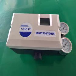
sart positioner EXDIICT6
- Model Number: ALP2300-SERIES
- Brand Name: AERLP
- Place of Origin: ANHUI, United States
- Minimum Order Quantity: 1
- Supply Capacity: 3000/month
- Payment: T/T
- MemberShip: Free Member
- Inquiry Now
ALP2300-SERIES sart positioner EXDIICT6 Description
1. Overview
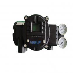
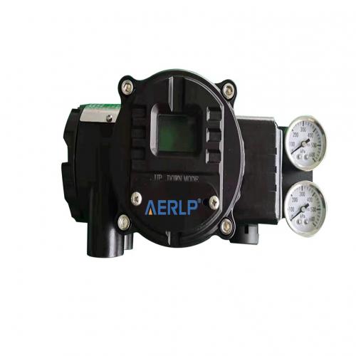
1.1 Performance profile of the ALP210 The ALP210 uses a microcontroller electronic control unit, the PID exact algorithm of the pneumatic instrument. With keys, LCD dot array screen display, HART communication and MSBUS communication functions. Adopt modular structure, compact, strong, reasonable design. High cost performance, simple maintenance, to avoid unnecessary user costs.
operation panel
ALP locator built-in operation panel, equipped with 3 keys and LCD LCD display, simple and convenient operation. With simple debugging and automatic, manual operation switching function. Can facilitate the stroke adjustment and automatic sealing function to open and close. You can also view the run parameters.
Pneumatic performance
With many years of experience in pneumatic instrument design, the carefully optimized single-action and dual-action amplifier structure brings great convenience to users and saves the use cost. Modular structure, easy to repair, replacement. The ALP locator is equipped with two output interfaces, blocking an output interface is a single-action valve positioner, and can also change the interface to change the form of the valve action.
communication
ALP has two modes of communication, MSBUS can be used to connect to a dedicated operator or computer, HART communication module (not standard, selected when purchase) can be connected to HART operator or (through HART-adjustment demodulator) to the computer.
signal output
ALP has the valve position feedback function (not standard, selected
Instructions Version Number::20/01-2.01-CN
function when purchase), using the two-line loop power supply technology, the power supply voltage drop is less than 6VDC at 20mA. No calibration, automatic follow, the accuracy is better than 0.5%. modular structure
ALP adopts modular design structure, circuit board control module, pneumatic amplifier module, I / P conversion module, sensor module, can be very convenient maintenance and replacement.
Principle structure diagram
Instructions Version Number::20/01-2.01-CN
1.2 type specificationALP2XXX
Intelligent valve positioner
Model ALP2
X0
X
-X
X
Die-cast alloy aluminum shell, surface anticorrosion spraying
The LCD dot-matrix LCD screen display
Single, dual-action integrated structure
Direct travel and rotation are general design
Intelligent single-key debugging
Essentially safe
10
Explosive type
30
Basic functional type
0
With the valve position feedback function type
1
With the HART communication function type
2
Overall (type with valve feedback and HART
communication)
3
With FF bus
4
With a PROFIBUS bus
5
single-action
S
double-acting;difunctional
D
Electrical interface NPT1 / 2, gas source interface NPT1 / 4 (US
standard)
N
Electrical interface M20x1.5, gas source interface RC1 / 4
(national standard)
M
Instructions Version Number::20/01-2.01-CN
the key technical indexes
1. Input signal range: 4~20mA; the dividing range is 4~12mA and 12~20mA. 2. Feedback signal range: 4~20mA; the range is 4~12mA and 12~20mA.
3. Equivalent resistance: 425 Ω (625 Ω; HART protocol type)
4. Control accuracy: 0.5%
5. Lineity: 1%
6. Sensitivity: adaptive; or artificially set during which the period is 0.1%~5%
7. Gas supply pressure range: 0.14~0.55MPa
8. Gas consumption: static gas consumption is 50NL / h ; dynamic unassessment
9. Environmental conditions: temperature: -25~ + 60℃ ; humidity: 90%
10. Dynamic resistance: 2g (5~200HZ)
11. Safety parameters: Ui=28VDC;Ii=93mA;Pi=0.65W;Ci=1nF;Li=0.2mH;
12. Storage conditions: temperature: -40~ + 85℃ ; humidity: 95%
13. Protection level: IP66
Programmable parameters
1. Enter the starting point range: 4~12mA
2. Input end point range: 12~20mA
3. Input signal: convertable direction
4. Output signal: convertable direction
5. Off limit: starting point 0~10% End point ranged from 90% to 110%
6. Trip adjustment: starting point 0~30% End point is 70% to 100%
7. Trip time: 0~200S
Instructions Version Number::20/01-2.01-CN
8. Output characteristics: linear, 1:25,1:50 optional
9. Tolerance band: 0.1%~10% adjustable
10. PID parameters: tunable
ALP210 Main part names and functions
component
explain
body
Housing, upper cover, position sensor
Control panel, circuit unit
Control circuit board, shortcut operation keys
I / P electrical conversion module
Telecom signal-to-gas signal conversion module
pneumatic amplifier
The amplifier will generate the gas signal from I / P to control the actuator intake and exhaust.
Pressure gauge connection module
Indicates the input and output pressure.
Feedback rod
Transfer the openness signal to the position
sensor.
Additional circuit unit
Integrated in the control circuit board when an
additional 4-20mA position feedback unit or a
HART protocol unit is selected.
2、Explosion-proof, safety and wiring
2.1 Security overview
This product has passed the strict factory test and meets the requirements of IEC3836.4:2010. In order to ensure this good condition during the running time, the requirements of the instructions and valid documents and certificates must be followed, and the routine safety regulations must be followed when operating the equipment. In addition to the regular safety procedures, descriptions or operating instructions along with specific safety tips. Only pay attention to all safety tips, can effectively prevent personnel and the environment from harm, reliable and normal use of equipment.
2.2 Use of regulations
Instructions Version Number::20/01-2.01-CN
The ALP210 locator is designed and manufactured for the application of "pneumatic output valve locator for industrial process control system", and is installed on the direct stroke or rotary pneumatic actuator as required in the instructions. This equipment can only be used as specified in the operating instructions and parameters. Any other use of violations will not be permitted. Input signal circuit / feedback output circuit wiring must meet the explosion-proof requirements (see 2.3 Safety
explosion-proof requirements for details) The maximum allowable ambient temperature range is-40...65 C Do not repair the circuit part and remove other explosion-proof related devices without authorization.
2.3 Anti-explosion-proof requirements
2.3.1 The product must be matched with the safety grid certified by the explosion-proof inspection agency to form the primary safety
explosion-proof system. Safety parameters are as follows: Input circuit (terminal ± IN) Ui=28V,li=93mA Pi=0.66W,Ci=1nF,Li=0.2mH Output
circuit (terminal ± OUT) Ui=28V,li=93mA Pi=0.66W,Ci=1nF,Li=0.2mH 2.3.2 The connection between the product and the safety gate safety end shall be a shielding cable with a section of> 0.5mm2, and the shielding layer must be grounded. Cable distribution capacitance and inductance value must be less than the safety value. 2.3.3 The safety gate is
installed in a safety place, and it must comply with the operating
instructions. 2.3.4 Users shall not change the electrical components in the products at will. 2.3.5 When installing, using and maintaining the products, users must comply with both the Power Plant Design Code and the relevant GBV3836.15-2000 regulations of the "GB50058-92". ”2.4 Wiring 2.4.1 Input and valve position feedback control signal The input and feedback signals of ALP210 shall be used in explosion-proof situations, with the range of 4~20mADC (limit value 3.8-24mA). Signal cables: To
Instructions Version Number::20/01-2.01-CN
prevent external interference signals, shield cables with a maximum length of 1280m are recommended. Control cables are laid separately from the power cables.
2.4.2 Distribution diagram of wiring terminals
2.4.3hookup When using the ALP210 intelligent valve positioner in
the explosion-proof occasions, it must be
wired strictly in accordance with the
explosion-proof requirements, and the
safety grid used must be certified by the
national explosion-proof safety department
2.4.4 Safety and explosion-proof
parameters Input side: Ui=28V;Ii=93mA;Pi=0.66W;CI=1nF;LI=0.2mH
Feedback side: Ui=28V;Ii=93mA;Pi=0.66W;CI=1nF;LI=0.2mH 2.4.5 Input
signal wiring The ALP210 uses the 4-20 m A second-line technology, with no additional power supply, and the maximum drive voltage is less than 8.5VDC. The wiring method is the same as normal valve positioners and is compatible with existing DCS systems. Use in the explosion-proof area must be wired according to the explosion-proof requirements.
2.4.6 Valve position feedback signal wiring ALP2101 and 2103 provide valve position feedback modules, which transmit data between (withstand pressure 1500V) without co-mode interference. The voltage drop at the DC20mA output is <8VDC, with a load capacity of> 800 Ω under the DC24V
Instructions Version Number::20/01-2.01-CN
power supply condition.
2.4.7 Communication with the PC machine ALP2102 can communicate with PC through HART-FSK_MODEM. HART-explosion-proof safety certified
FSK_MODEM products shall be used in explosion-proof cases. PC shall be placed in a safe area and shall not be brought into the unsafe area on site. Suppliers can be contacted about the monitoring software.
2.4.8 Cable casing A M20x1.5 or RC1 / 2 screw hole is provided on the left side of the housing, with a cable sleeve waterproof connector to
penetrate the lead and lock the connector.
Instructions Version Number::20/01-2.01-CN
3、install
ALP Positioner more convenient support back-back valve installation.
Single action installation diagram
3.1.1Installation of a single-action direct-moving valve
Installation steps:
1、Install the feedback travel pin and mounting plate
on the valve first.
2、When installing the locator, need should add a cushion column. Pass the travel pin into the feedback rod chute and pass through under the wire card to remove the gap.
3、Adjust the chute feedback stroke pin to
screw of the
ensure that
9
Instructions Version Number::20/01-2.01-CN
the corresponding feedback rod rotation angle is within the ± 30 (60) allowable range within the full travel range of the valve. Pay attention to adjust the outgoing shaft length of the feedback travel pin to avoid
touching the positioner when working.
4、ALP series localers display angle in
factory state to guide proper installation
with minimum working angle 30.
5. Connect air pipe, each section of
gas pipe should have at least two elbows,
so as to facilitate disassembly and
maintenance.
6. See the relevant chapters of 4.2
for commissioning.
3.1.2Installation
of the dual-action
direct-moving valve
The installation of double-action direct valve is basically the same as single-action direct valve, the outlet has 2 OUT1 and OUT2, the output of OUT1 is
synchronized with the input signal, the signal
increases the output pressure. As shown in the figure above, increase the signal valve to open.
3.1.3Installation of the rotary valve
ALPSeries of intelligent valve positioner in the rotary valve installation is more convenient and fast.method of erection:
1. Install two lower mounting plates on the actuator first, and the screw should not die for the subsequent adjustment of the central
position.
Instructions Version Number::20/01-2.01-CN
2. 2. Install the feedback transmission screws with a height of 30mm. Note that the fastening screw direction is aligned with the positioner tolerance working direction. As shown in the figure.
3、Attach the upper mounting plate to the bottom of the locator and then align the actuator center to the lower mounting board. Tighten the lower mounting plate and the drive shaft lock screw after confirming that the actuator exit shaft and the actuator drive screw are normal.
4、4. Turn on the signal above 4mA (when the locator is in the factory state), and verify whether the ventilation is within the ± 60 allowable working range.
Instructions Version Number::20/01-2.01-CN
4、 basic operation 4.1control panel
When the ALP210 series
positionator is powered on for the
first time, the second line shows the
AERLP, which in the manual state,
showing the working Angle of the
positionator feedback rod (shaft),
which is more convenient for
installation and debugging. After completing the automatic debugging, the trip percentage is displayed and can be switched between manual and automatic. It can be restored to the factory state by the reset method. MODE — Mode key, used for automatic and manual switching. The second line of the automatic status shows "AOUTMA", and the manual status shows "MANUAL". UP-rise key, the manual state control of the opening of the valve, the automatic state is used to display the input current value. DOWN — Drop key, manual state control valve closing, automatic state used to display I / P drive value.
4.2Quick debugging method
1. Straight action valve debugging —— input 18mA, press UP and
MODE keys, keep 5S to release the button, display "ADL_L", and enter the straight stroke valve for automatic debugging.
2. Rotary valve debugging —— input 18mA, press DOWN and MODE keys
simultaneously, keep 5S to release the button, display "ADL_R", and enter the rotary valve for automatic debugging.
3. Restore the factory value of ——, input 12mA, press UP and MODE keys
to keep 5S, display "REST", and the "REST" display disappears after successful reset.
4. Reset the starting point ——. Enter the starting point value (4mA)
in the automatic state, and press the UP and MODE keys simultaneously to raise the starting point. Press both DOWN and MODE to lower the start
Instructions Version Number::20/01-2.01-CN
point and turn on enforcement.
5. Reset the end point ——. Enter the end point value (20mA) in the
automatic state, and press the DOWN and MODE keys simultaneously to reduce the end point. Press both UP and MODE to raise the end point and turn the force function on.
6.Press the UP key for the input express display —— automatic status
to display the current input mA value.
7. Press DOWN on the —— to display the drive current value.
8. Switch —— to 16mA and press MODE (mode) for 3 seconds.
4.3 Flow chart of automatic debugging and stroke adjustment Automatic debugging (self-setting) flow chart full degree (end point) adjustment flow chart
Instructions Version Number::20/01-2.01-CN
communication
The ALP series product supports 2 communication modes (please contact the dealer for the communication software) HART communication, you can connect to the HART manipulator or computer
Connect the computer USB port through the MSBUS converter
You can also connect directly to the MSBUS
handler
Instructions Version Number::20/01-2.01-CN
4.4 Parameter setting,
modification and communication ALP210 provides a quick mode of operation for easy use and debugging. The modification of other functions and parameters of the intelligent locator must be realized through the hand operator or HART communication.
The ALP210 locator parameter options table
item
number
function declaration
optional
parameters
unit
Factory
value
1
Enter the signal starting point
4.00~12.00
mA
4.00
2
Enter the signal endpoint
12.00~20.00
mA
20.00
3
Positioner
operating
characteristics
Linear 1:25 /
1:50 (Equal
Percentage) 50:1
(Open quickly)
linear
4
Positioner
working
direction
Air opening
(reaction) Gas
clearance
(positive)
Air opening (reaction)
5notes①
Valve starting direction
Air opening
(reaction) Gas
clearance
(positive)
Air opening (reaction)
6notes②
start of a run
0.0~50.0
%
0.0
7notes②
stroke end
50.0~100.0
%
100.0
8notes③
sensitivity
0.1~10.0
%
-
9notes④
Full trip time
0-200
S
0
10notes⑤
scale
0.5~10
-
11notes⑤
integral
1~500
S
-
12notes⑤
differential
0.1~10
S
-
13
I/Pmedian
30.0~70.0
%
50.0
Instructions Version Number::20/01-2.01-CN
14
Actuator
compensation
2~200
-
15
Full open point signal cap
90~110
%
102.0
16
Lower limit of full off signal
0~10
%
0.5
Note ① : This item is generally obtained through automatic debugging and self-inspection, and the setting must be in the same direction as the actuator. Note ② : Automatic debugging can be obtained by
self-detection. Note ③ : When the automatic debugging cannot meet the requirements of the valve (the valve resistance is too large or there is a slight bite bite phenomenon), the sensitivity range needs to be appropriately increased to overcome the fluctuation. Note ④ : When the full trip is set to 0. Note ⑤ : You cannot change it easily until the parameter meaning is determined, otherwise it will cause abnormal work.
Instructions Version Number::20/01-2.01-CN
HART communication software in Chinese version Through the
FSK-HART-MODEMM and connecting to the PC machine, you can consult and modify all the parameters, and execute the commands. First, select the correct communication interface (USB port), and then press the
"Instrument Communication Test" button, after successful communication, other buttons can be activated. To select HART communication compatible
upper instrument for communication, the system with security
communication must also consider HART protocol compatibility issues, can connect a 250 ohm resistance in the circuit to improve the quality of transmission signals. The software is available through the supplier.
4.5 Calibration of the input signals Each instrument has calibrated the
input signal before leaving the factory, and the current input mA value can be read by pressing the UP key automatically. Different standard sources and changes in ambient temperature can cause small errors and do not affect the use. For more demanding occasions, the user can go through the circuit Built-in switch or hand operator and HART communication software on the board. Enter the 4 and 20mA standard current, respectively, and press the built-in switch or handler or HART communication software calibration command. Note: First calibration is 4mA and then calibration is 20mA.
5、Fault and exclusion
5.1 General Provisions The ALP210 is a precision instrument, which can
be installed in different models of regulating valves, with accurate setting and correction of electronic components and mechanical components, easy to adjust and set. When operating the ALP210, the light fault does not affect the normal operation, and only when a serious fault occurs, if you continue to use it, it will damage the intelligent locator, and it is generally not recommended to repair it by itself.
Instructions Version Number::20/01-2.01-CN
5.2 Troubleshooting method The ALP210 has no output (no gas output) 1)
Check whether the input 4~20mA signal of ALP210 is normal, and whether the display window can display the characters normally. 2) Check whether the gas supply meets the requirements of 0.15~0.6MPa, and check whether the pressure indication on the pressure gauge module is normal. 3) Switch to the manual state, and use the "UP" or "DOWN" switch valve to check whether the output pressure gauge has changed, and whether the valve is stuck. 4) Whether the feedback connection parts are loose and fall off. Control valve operation is abnormal (gas source, but regulating valve action is not normal) 1) Check the air supply pipeline for air leakage. 2) Check whether the feedback rod is loose. 3) Check whether the valve has a bite point, and the resistance of the sealing packing is too high. Adjust the tuning sensitivity (dead zone) parameters appropriately if the control requirements are not reduced.
5.3 Determine the fault of the locator with the display Working in Auto:
Press the UP key —— to display themA value of the current input current. Determine whether the input signal is normal. Press the DOWN key —— to display the percentage of drive values currently output to the I / P converter. Used to determine whether the I / P converter and amplifier work properly.
5.4 Maintenance and return to the factory
1) Maintenance of the throttle: remove the circuit board, see the throttle
screws on the pneumatic amplifier, remove the throttle hole dirt and reinstall the throttle.
2) Maintenance of the relay: the fault of the relay is mainly caused by
the aging of the diaphragm, so you only need to replace the new diaphragm.
Instructions Version Number::20/01-2.01-CN
3) Circuit board maintenance: the circuit board has been treated against moisture, but the site must avoid direct water entry. In work with large dust, open the upper cover regularly and clean the dust from the locator and circuit board with instrument wind. In the long-term shutdown state, the power transmission should be sent for 30 minutes every 3 months to prevent the internal capacitor from aging.
4) Return to the factory regulations: if there is a non-gas road fault,
do not remove and repair without authorization, so as not to affect the explosion-proof performance and safety! Be sure to return to the
manufacturer for repair.
Instructions Version Number::20/01-2.01-CN
6、outline dimension;
Instructions Version Number::20/01-2.01-CN
7、Attachment selection
Direct trip feedback rod
selection
Travel range
Backstick installation
15~50mm
40~80mm
60-100mm
Length A(mm)
60
85
130
150
Order number
AK1050
L50
L75
L100
Straight trip mounting plate selection
Backstick actuators do not require
mounting boards, and other actuator
mounting boards can be common.
Direct trip feedback travel pin selection The backstick actuator has with own travel slot ute requires no feedback travel pin. Other actuators have stroke pins for M6, or reconnect stroke pins through a chute plate. The length of the outgoing shaft of L should be adjusted according to the specific situation, to ensure that the valve moves. Rotary
installation assembly The rotary mounting plate is an adjustable general assembly, and can generally be installed on different cylinders. Pressure
Instructions Version Number::20/01-2.01-CN
gauge component selection The
single-acting assembly (2 pressure gauges)
indicates the input and output pressure,
respectively. Order number: Type I Y001
dual action assembly (2 pressure gauges)
indicates the pressure of two outlet ports.
Order No.: Type II, Y002
Pressure gauge component selection The
single-acting assembly (2 pressure gauges)
indicates the input and output pressure,
respectively. Order No.: Type I Y001
The dual-action assembly (2 pressure gauges) indicates the two outlet pressures, respectively. Order No.: Type II, Y002
| Equivalent resistance: | 425 Ω (625 Ω; HART protocol type) |
|---|---|
| Control accuracy: | 0.5% |
| Lineity: | 1% |
| Sensitivity: adaptive; or artificially set during | 0.1%~5% |
| Protection level: | IP66 |
| Storage conditions: temperature: | -40~ + 85℃ |
| ex proof | exdIIct6 |
| Gas supply pressure range: | 0.14~0.6MPa |
Retaled category: Angle Valve
Hot search: sart positioner, positioner, valve positioner, control valve, valve